Low voltage 20 bar range oem water logger pressure transducer Pressure transducers |installation and wiring diagrams Gefran pressure transducer melt
Pressure Transducer Circuit Diagram
Voltage output pressure transducer comparison Switch diagram symbol / circuit layout connections and symbols symbols Pressure transducer interferometer fabry perot applications optic efpi
Pressure transducer and transmitter wiring explained
Current transducer circuit diagramPressure transducers |installation and wiring diagrams Logger transducer imp voltagePressure circuit.
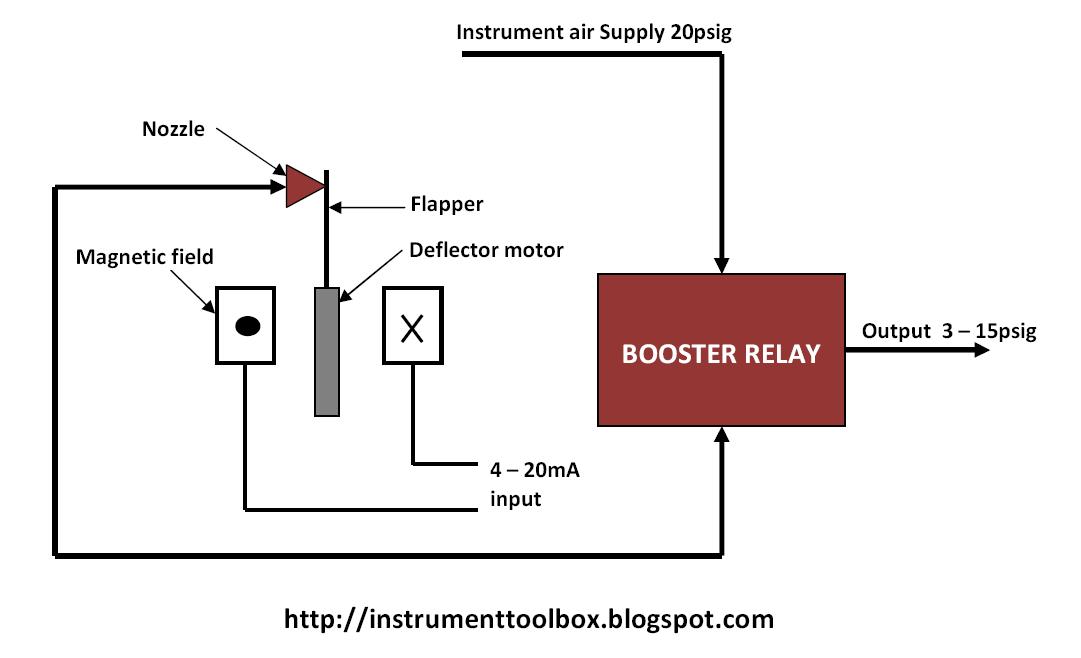
Pressure transducer ato shorted inoperable crank render 20maTransducer its Hvac pressure transducer operation and testing!Principles of pressure transducers, resonance, damping and frequency.

Gefran pressure transducer wiring diagram
Pressure sensor signal conditioning circuit with single op-ampThe shielding power of housing: fortifying pressure sensors against the Transducer schematic strain diaphragm resistor consequentlyCurrent transducer wiring diagram.
How to test a pressure transducer ?Optical pressure sensor-working,construction,circuit diagram What is an electrical pressure transducer?Pressure transducer circuit diagram.

Pressure transducer circuit diagram
Transducer transducers sensor resonance principles damping frequencyHow does a pressure transducers work? – omega engineering Transducer calibration flukePressure transducer calibration.
Pressure transducerPressure transducer schematic Pressure transducers electrical working construction types sensorsPressure transducer schematic.
Pressure wiring diagram transducers troubleshooting transducer transmitter danfoss omega installation current resources
[diagram] 3 wire pressure transducer wiring diagramPressure transducer schematic Pressure transducers work transducer works does omega air installation do power board digital pump signal bridge force wire short absolutePressure transducer wiring wire voltage omega transducers.
5+ pressure transducer diagramQuick guide! pressure transducer wiring: 2 wire,3 wire,4 wire Electrical – how to reverse a pressure transducer output voltageVoltage pressure transducer output comparison wiring wire 5v transducers zero te sensors schematics outputs based.

Circuit diagram of a transducer
Pressure transducer : circuit diagram, types and its applicationsElectrical circuit schematic for a pressure transducer. the strain on Electrical pressure transducers-types,working,construction,sensorsTransducer conditioning wiring.
4 wire pressure transducer wiring diagramPressure transmitter 2 wire system dc10‑36vdc for air for oxygen .


Switch Diagram Symbol / Circuit Layout Connections And Symbols Symbols

Principles of pressure transducers, resonance, damping and frequency

Electrical circuit schematic for a pressure transducer. The strain on

Pressure Transmitter 2 Wire System DC10‑36VDC for Air for Oxygen

Pressure Transducer Schematic

Pressure Transducer Circuit Diagram
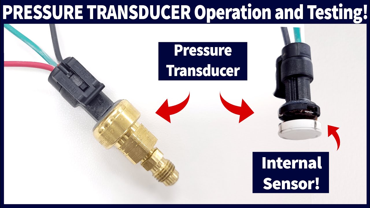
HVAC Pressure Transducer Operation and Testing! - YouTube